
AAWG
Athermal Arrayed Waveguide Grating
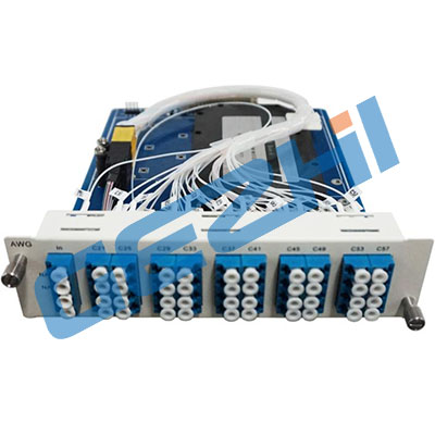
■Product Description
AAWG:Athermal Arrayed-Waveguide Grating mainly is used in DWDM system. It transmits signal by making different ITU-T DWDM wavelength signals multiplex to single fiber in receiving terminal. It decomposes composite signal into different ITU-T DWDM wavelength signal. The product has a low insertion loss, high channel insertion loss consistency, nothing external power supply and so on.
■Product features
♦ Low insertion loss
♦ High consistency channelinsertion loss
♦ Low polarization dependent loss
♦ High channel isolation
♦ Without power supply
♦ Excellent environmentalreliability
♦ High level of integration by plug-in design
■Performance index
|
Parameters |
Notes |
Specifications |
Units |
|
|
Min |
Max |
|||
|
Channels |
40 |
Ch |
||
|
Channel Spacing |
100 |
GHz |
||
|
Reference Pass-band |
Relative to ITU Grid |
± 0.1 |
nm |
|
|
ITU Frequency |
On ITU grid in C-band Even |
196.00 |
192.10 |
THz |
|
ITU Wavelength |
On ITU grid in C-band Even |
1529.553 |
1560.606 |
nm |
|
ITU Frequency |
On ITU grid in C-band ODD |
196.05 |
192.15 |
THz |
|
ITU Wavelength |
On ITU grid in C-band ODD |
1529.163 |
1560.200 |
nm |
|
Center Frequency Accuracy |
Maximum of the absolute deviation of the 3 dB center wavelength from ITU grid over all channels |
-0.05 |
+0.05 |
nm |
|
Insertion Loss |
Maximum of the insertion loss across the ITU pass-band over all channels |
6.2 |
dB |
|
|
Insertion Loss Uniformity |
Maximum insertion loss variance across all channels |
1.3 |
dB |
|
|
Ripple |
Maximum of the loss variance across the ITU pass-band over all channels |
0.5 |
dB |
|
|
0.5 dB Bandwidth |
0.5 dB from min Insertion Loss, full width, worst case polarization |
0.2 |
nm |
|
|
1dB Bandwidth |
1dB from min Insertion Loss, full width, average polarization |
0.4 |
nm |
|
|
3dB Bandwidth |
3 dB from min Insertion Loss, full width, average polarization |
0.55 |
nm |
|
|
20 dB bandwidth |
20 dB from min Insertion Loss, full width, average polarization |
1.2 |
nm |
|
|
Adjacent Channel Isolation |
Ratio of peak transmission to the maximum transmission over both adjacent pass-bands |
25 |
dB |
|
|
Non-Adjacent Channel Isolation |
Ratio of peak transmission in channel pass-bands to maximum transmission over all non-adjacent pass-bands |
30 |
dB |
|
|
Total Crosstalk |
Ratio of power in channel to power in all other pass-bands |
21 |
dB |
|
|
Polarization Dependent Loss |
Maximum ratio of transmissions over all polarization states, over the ITU pass-band |
0.5 |
dB |
|
|
Return Loss |
40 |
dB |
||
|
Polarization Mode Delay (PMD) |
In Reference Passband over all channels |
0.5 |
ps |
|
|
Chromatic Dispersion |
In Reference Passband over all channels |
-15 |
15 |
ps/nm |
■Ordering Information
|
P/N |
– |
Type |
– |
Channel number |
– |
Fiber interface |
|
AWG |
A:Athermal |
32:32CH@100GHZ |
LP:LC/PC |
|||
|
40:40CH@100GHZ |
SP : SC/PC |
|||||
|
44:44CH@100GHZ |
FP : FC/PC |